10/29/2007
Fuselage Formers Part 2
Greetings all. Here we have the full update on the former construction. I know the last one was just a tease, but I like to do these updates in chunks that make logical sense, and to tell you the truth, this part just took a long time. I am pleased to report though, that the results are very good so far. Of course, until it comes out of the mold and we see how strong it will be, there is still uncertainty, but I'm really encouraged. Anyhow, on with the details....
First up, I figured out where I thought formers should go. Some of this was subjective, other times it was dictated by where components needed to be. For example, landing gear is pretty well set, by where documentation shows it sticking out of the airplane. Secondly, I have a sense that this will want to be tail heavy, so engines should be as far forward as practical. Lastly, the wing tubes come out of the wing at a specific place, so the former to receive them should be in a particular place.
Once you figure out where you want them, actually making them is not as simple as it sounds. Remember, there is no solid 'plan' for this, so there is nothing to reference for a perfect former. They need to be made by hand, to fit the plane that we've made. To do that, I broke it down into several steps...
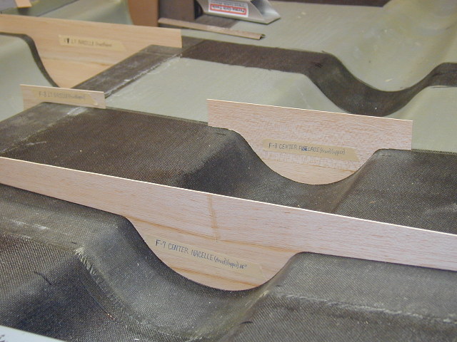
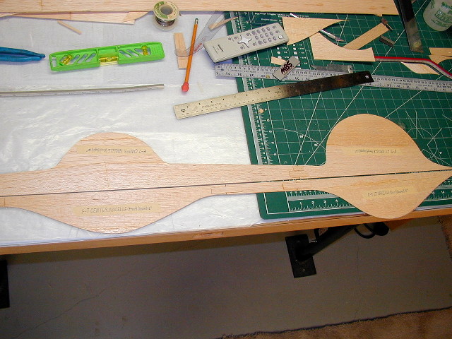
First up, balsa was carved, fitted, and sanded to conform to the curvature of the fuselage cross sections where formers were going.
Next up, other balsa was spliced in to join them.
You can see here, this quickly becomes a patchwork of pieces. But this is actually faster than trying to make one big one and making it fit all over.
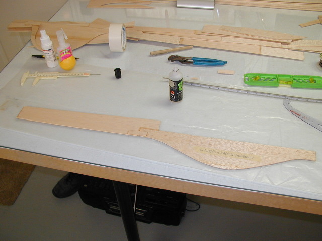
Next up, is what I think, a really smart solution to a problem you probably didn't even see coming.... What I've explained so far is fine for making one half of a former... But I need it to be a perfect fit, for both the top and bottom halves. With it laid open like a pair of clam shells, how do you do that? What you see here is a 6 foot 'straight edge' of balsa planks that have been trued as straight as I can make them. It is then put up next to the former half, then tack glued, and then cut along this line.
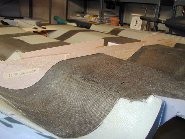
Here you see the result of doing the above process, for the top and the bottom. Then you just glue them together, and poof... You have your former that should fit the space when it's closed up.
Once I had a balsa template, I transferred that to 1/8th 5 ply, plywood, and started to make the 'originals' for the formers on a Dremel scroll saw. All of these that were being made, would never get a drop of glue put to them. They would just serve to make copies of later.
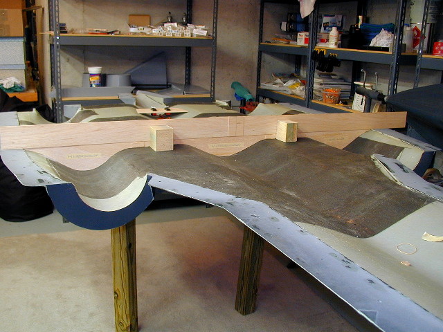
Here is shown the initial layout of the where the engines would go, and an initial engine mounting rail.
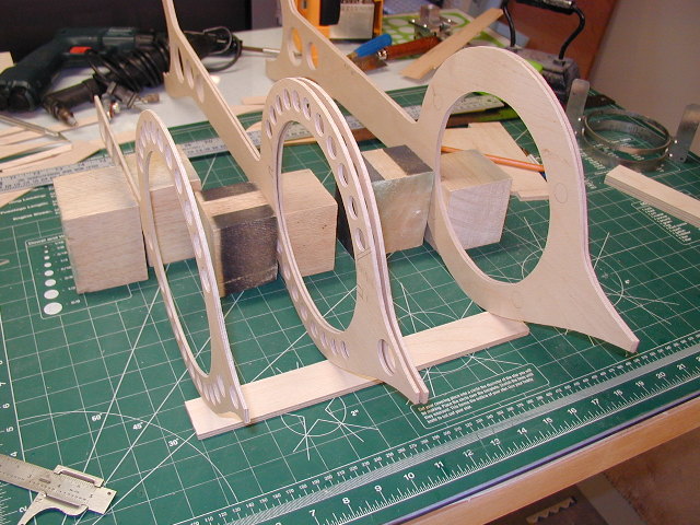
Once I got a height figured out of where the engine rails go, then they had to be leveled to give the proper incidence in the nacelle.
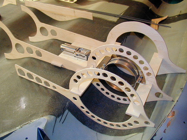
Once all this was figured out, notches were cut, in both the rings and the engine rails. This allowed for assembly later, that set everything about the rails perfectly, without having to measure everything, time after time. Also shown here is one of the main gear landing blocks. Here also, was a difficult task to get the interlocking notches and slots cut properly, so that they would set square in a fuse that has nothing flat or square to measure against.
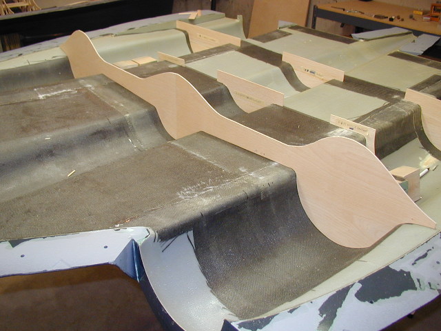
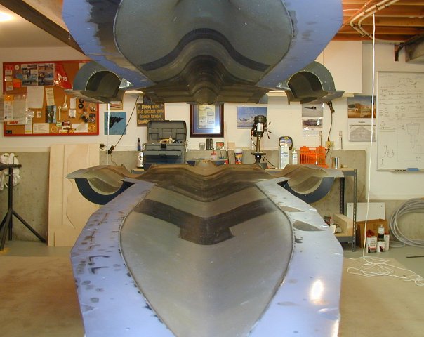
Once all the original formers were finished, I needed to confirm that they fit properly. This meant it was finally time to 'dry-fit' them into the mold's. Each mold half weighs about 125 pounds. I anticipated needing to lift and lower it many times to fine tune the fit, so, I installed this pulley system to make it a more controlled process. It worked great and took much of the grunting and groaning out of this process.
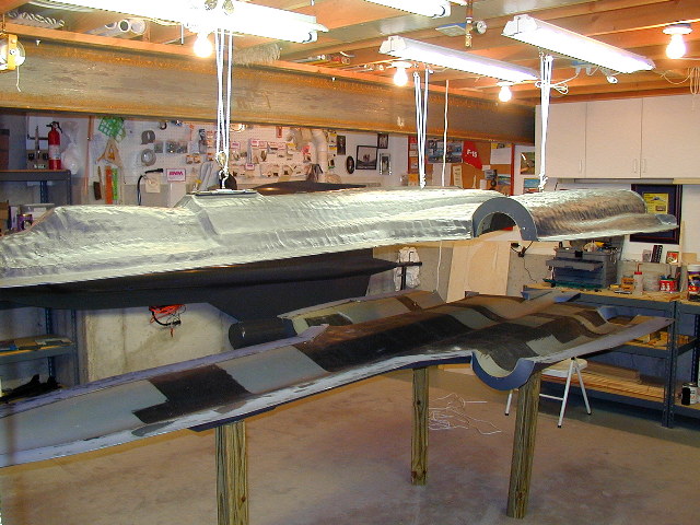
I just thought this view looked neat.
So, once all the parts were fine tuned on their fit, it was now time to make copies of them, to glue in the plane. I rough cut them out on a Dremel scroll saw. Then to get them exactly the same, I used a router, with a bit that has a ball bearing on the top. The ball bearing could roll along the top 'original' while cutting the bottom one to the exact same size. It took 6 months to make the originals. I copied their outline on the router in about 4 hours. Talk about feeling like you got a lot done one night...

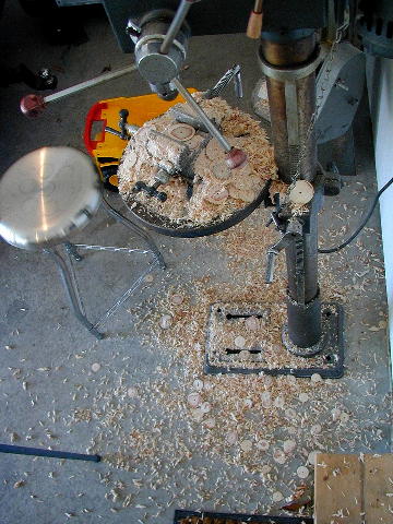
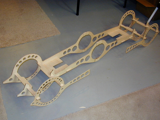
Next up was putting all the lightning holes in. For this I used a variety of Forstner bits. This part is really fun. Quite a bit of carnage throwing wood everywhere, but really fun.
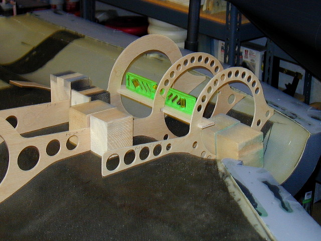
Here's a shot of the main engine / landing gear former assembly. I could pick this up as a solid unit, with just the locking tabs and slots holding it together.
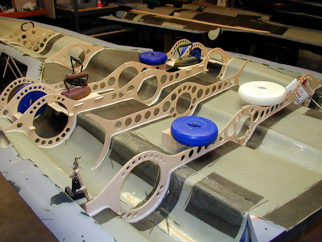
Time to break out the Aero-Poxy. One night, and about 5 cartridges later it was all glued in.
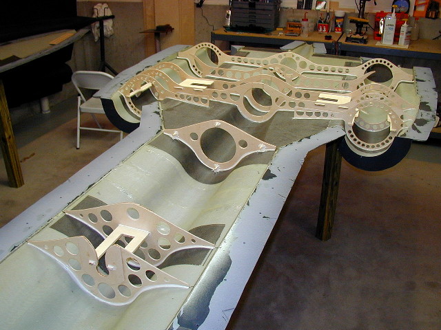
The next morning, all looks good. Next up, will be a few final details, such as battery trays, and a few servo trays. All this is building up to closing the shells together, and pulling this thing out of the molds.
Head back to the Main Page