12/21/2007
Wings
Things are moving along quickly now. Getting the fuse out of the molds went pretty well. It took about 90 minutes to get it free of the molds, about an hour to clean the PVA off, and then about 3 hours to clean up the molds. I am very pleased with the strength of it, and have no concerns with it being strong enough to be the first test plane. Jerry and I went opposite of each other on the wing roots / nacelle area, and tried to induce a twist on them, and I tried to twist it as hard as I could and they did not budge. I'm running a bit heavy of where I wanted to be, but not bad, and it's very strong. The empty shell of the fuse you saw in the last update, weighed 21.5 lbs, and I was shooting for under 20, so not too far off the mark.
At this point, it's like I've just opened a kit that has arrived in the post, so it will be fairly conventional model building from here on out. Other than the fact that I'm just making this up as I go along, as Jerry often points out....
First order of business, was I wanted to get the wings attached and the outboard elevators up and running. Below you'll see several shots of this process.
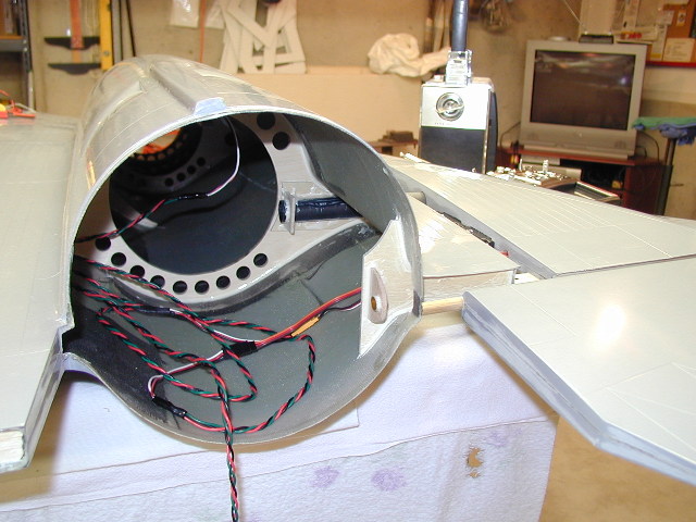
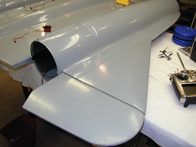
Here, if you look up into the nacelle area, you'll see a black carbon tube. This is a 7/8 inch size, and from what I've learned these should take 350-400 lbs of force before they would fail. You can see the wing is about an inch pulled out, to show the inner carbon tube that will plug into the female part in the wing root. Also, you'll note a small piece of brass tubing with a dowel close to it. See below what that's for.
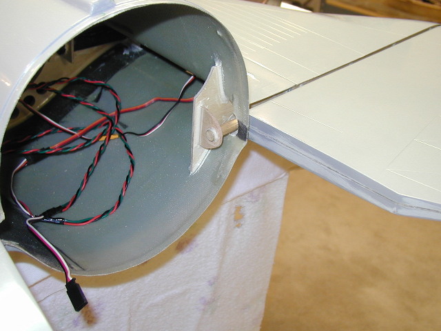
Here, you'll see this part fully seated now. For the wings to plug in, it made sense for the elevator to be permanently attached to the wing. This meant that there was a large part of the elevator not supported, inbound of the wing root. So, I've inset a half inch dowel, into the end of the elevator, that when the wing is fully seated, slides into a brass tube, as a 'bushing'. This supports then inner part of the elevator nicely, and feels quite solid.
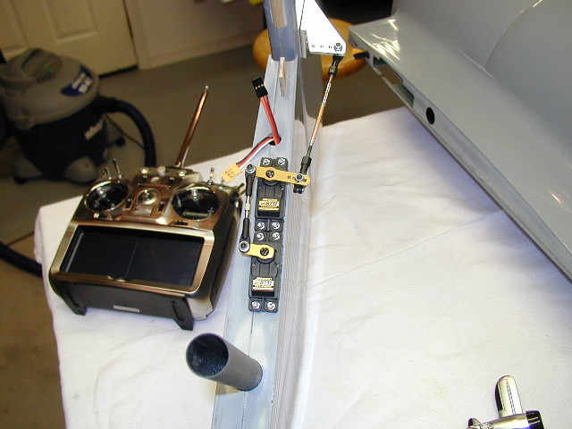
Speaking of solid.... After doing the math on the size of elevator, and the speeds it's being designed for, I calculated I would need 34 lbs of force to be delivered down the push rod. OUCH. That is allot of power needed. I thought that a JR 8711 with 400+ oz of torque would be enough initially, but the math dug out the fact a single servo would not do the job. Shown here are 2 of these servos ganged together, with a titanium link between them. That's a full 50 POUNDS of power available down the push rod! This stared to get me worried, about that amount of power being delivered all along the linkage train. At the top of the photo, you'll see a hand crafted aluminum control horn, with drilled and tapped holes for the push rod, and a full 1.5 X 1.5 inch base secured into the ¼ inch plywood block that was glued to the interior of the elevator. This block was reinforced also, to the top wing skin, so the loads could be dispersed.
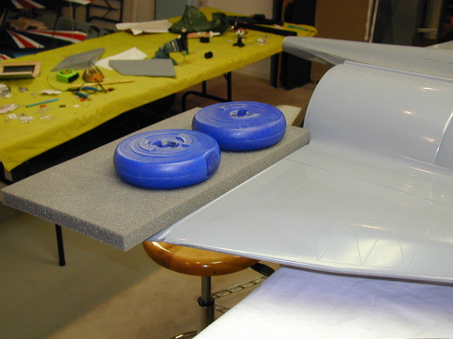
It just seems wrong, putting barbell weights on your airplane. But, I had to know that it was at least close to being able to handle it when it was done. This is 10 pounds of weight, on average in the center of the elevator. Given the moments of leverage, this should be about 25-30 pounds of force to the servo arm and linkage. The servos, and all parts of the linkage train, accurately, and smoothly could move the elevator up and down with this weight sitting on it.
Final shot of completed wing / outboard elevator assembly. Next up, will be the inboard elevators.
Head back to the Main Page