2/12/2008
Rudders
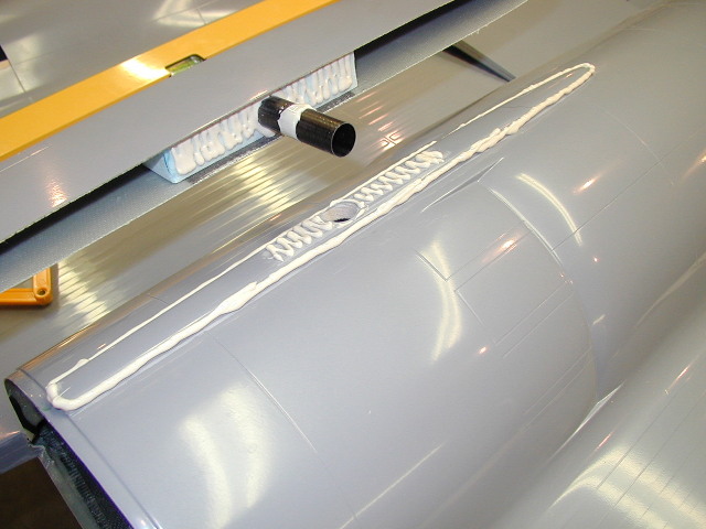
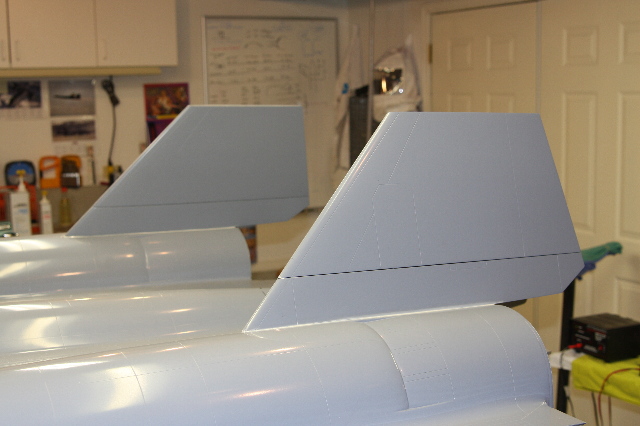
Rudders and the rudder bases are on and finished, and turned out great! I was very pleased with how solid this section has turned out. When making the fuse plug, I put in these 'key's' on top of the nacelle's that would help in this step, and they helped big time. The alignment is set, and then just glue the rudder bases's on with the correct angle (15% banked inward). See bellow for the details of this part of the project.
I've got a carbon tube that goes through the rudder base and on into the nacelle, that will act like a bushing for the pivoting full flying rudders. I inset a section of solid foam in the rudder bases when we made them, to help carry through the loads of this pivot point to the surrounding base and fuse. After the glue dried here, I was very pleased with how solid these were.
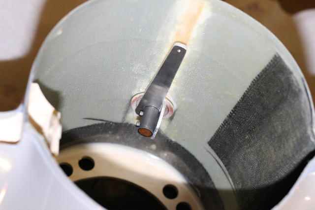
I used a smaller carbon tube to go down through the base. The top of this tube is glued in quite solid to about 75% up into the rudder, which also has solid foam in this area, much like the rudder base does. So with this now sticking down into the nacelle, I then fashioned a control arm onto it out of angle aluminum. This took much pondering, but once I had it's concept down, making the parts went pretty quickly. The tip is tapped and threaded for the control arm.
Here you see the servo for articulation of the rudder. This took quite a bit of pondering as well, to get good clearance for the top of the arm against the fuse, and to maintain nice 90 degree angles with the short push rod. With a 4.25 inch long arm, the mechanical advantage the servo has on the huge rudder is very nice, and it only needs the single servo to handle the large surface. Control movement is just over 2 inches on either side, when measured at the rear of the rudders.
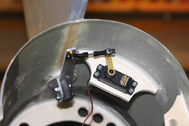
Finished installation.
Head back to the Main Page