10/30/2008
Turbine Time
The paint stirring sticks, that some call props are now off the plane, and its time to get it geared up for how it was meant to fly, on turbines. Last you recall, a test flight had been successfully conducted with 2 SuperTiger 3000s for power. Since then, the temporary fire wall's have been ground out, engines removed, glow fuel tanks taken out, and its now ready to fly on jet engines. Read below about the conversion steps up to this point.
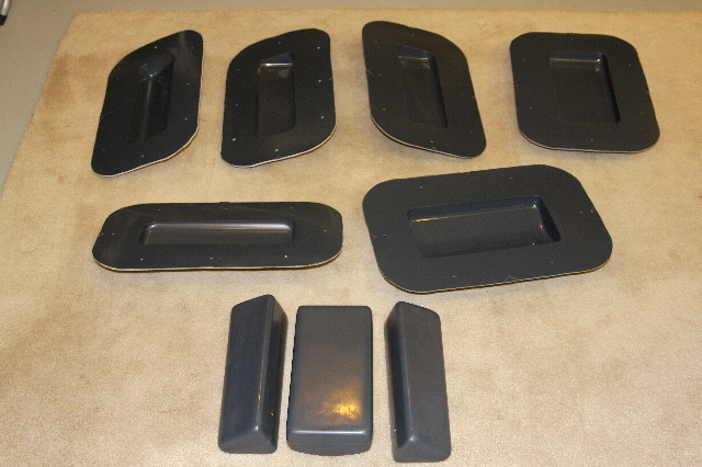
The glow engines just needed a 24 ounce tank per engine. Turbines suck a whole more fuel than that for a flight. Also, because were talking about so much fuel here, it really needs to be on the center of gravity, as close as possible. There was no way to put in off the shelf tanks, and have enough capacity, so I had to set about making my own fuel tanks. I used the previously mentioned techniques, to make 3 tank plugs that were to be the final size of the fuel tanks, and then cast molds off of them, just like Ive done on all the prior parts. A fun side note was that to determine how much fuel these would carry, I used a big tub, in a bigger slop sink, and used water displacement techniques. I could estimate very close, the ultimate fuel capacity this way, on tanks that have many compound curves. Total fuel system capacity, 275 ounces, to be shared by 2 engines.
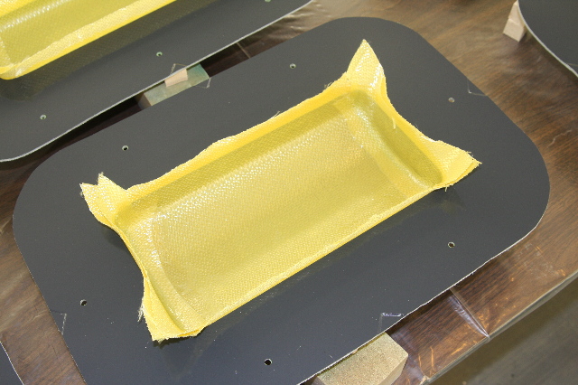
Here you see 2 layers of 6 ounce Kevlar being laid up into one of the molds. This is some strange stuff to work with. It laughs at normal scissors. Sanding or grinding it after it cures, produces just fuzzed up material that then must be cut away.
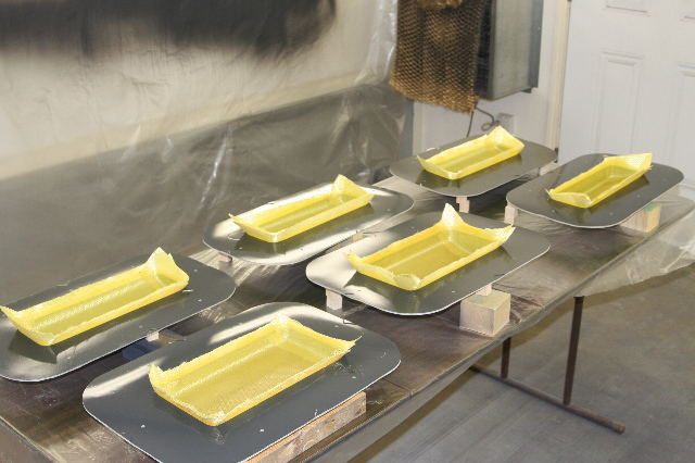
3 tanks, each with a half = the 6 molds you see here, with their halves having just been laid up. It also took 6 Dremel cut off wheels to cut the excess away after they setup. This is some seriously tough stuff.
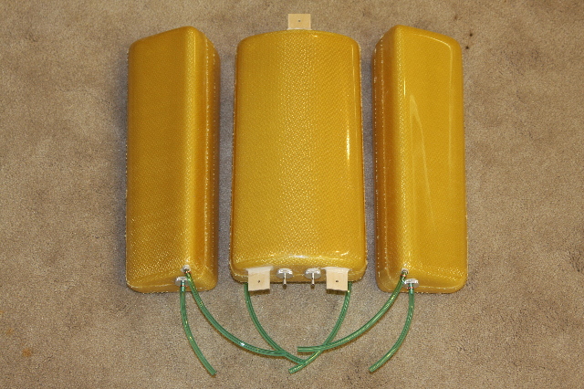
The final results. Im very pleased how they turned out. The center tank is upside down here, to show off its mounting brackets. Essentially, 2 wing root tanks will feed into the larger center tank. Then 2 pickups on the center tank feed 2, 6 ounce header tanks. The header tanks, each have a geometrically centered pickup that feed each engine.
Next up are 2 tailpipes made by Tam. Tam is quite the artist in pipe making and Im very pleased with these. They are dual walled and long...39 inches. Here you see the aft mounting in the turkey feather area.
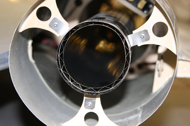
To mount the front of the pipe, Ive got these 3 short legs you see here. By using the 6 bolts, I can angle the legs a bit to get the pipe dead center on the exhaust of the engine.
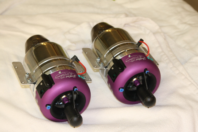
My 2 jet engines, 2 JetCat 120 SEs. (insert Tim Taylors, arwww, arwww arwww). They are kero start, but just for getting mounting worked out, I had 2 glow plugs in there temporarily to keep the dust out.
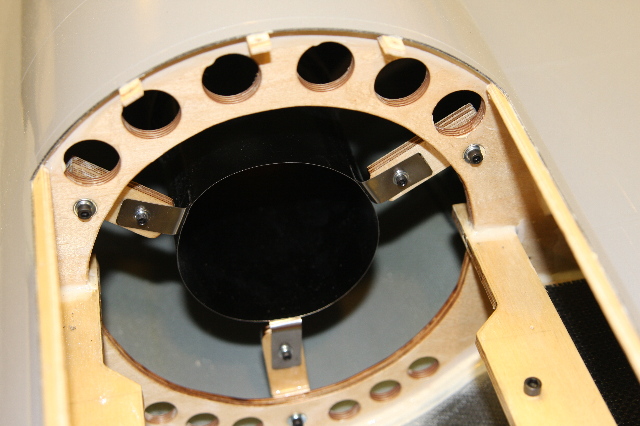
Right engine mounted and ready. Youll note the kero start, and the fod screen. Eventually, these engines will have a full bypass and the inlet spikes will be put in. Both are projects for this Winter.
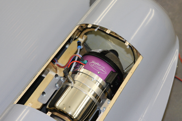
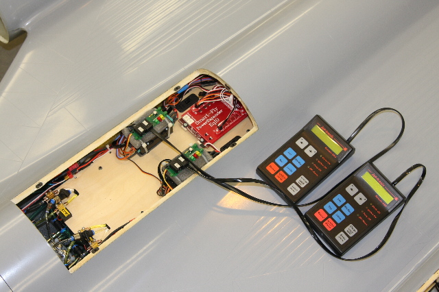
Main equipment tray shown here. It looks crowded in places and sparse in others on purpose. There is a lot of additional equipment to go in here yet, such as air systems and servos, but the basics for the turbines and receiver are here. Below and to the sides of the equipment tray are the main fuel tanks. Its funny, that with a 13 foot long airplane, how it seems everything needs to go into this single spot...
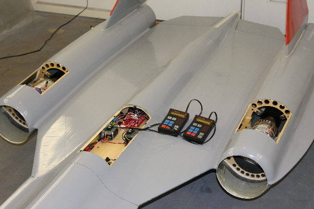
Completed installation that shows the location of the main equipment hatch. The hatches over the engines have many BVM screws holding them down, and are not to be removed every flight; just for service issues. However the center hatch will be removed for every startup and shutdown. It is through here that you can also reach in to tighten the bolts that hold the 2 fuse halves together. At this point its ready for turbine test flights. My hope is to get a couple in before the winter weather sets in. If not, it will have to wait for Spring. The temporary landing gear are still on the plane as the turbine issues are worked out, and further testing is done to see if its structurally sound at higher speeds. Next up on the plate, is to make the tip of the nose and tail, engine bypasss and inlet spikes.
Head back to the Main Page