1/8/2009
Main Landing Gear Struts
The temporary landing gear I made to conduct early test flights got the job done, but just barely. I peeled off a couple tires on what was pretty good landings. Not surprising, considering they were inexpensive foam hobby shop tires, that were being asked to carry a 65 lb airplane on 60+ mph landings. It was now time to start on the real landing gear.
For retracts, I'm using Tom Cook's Jet Model Products MK30's. They are very strong, simple and reliable. Plus they have a very low profile, to fit in what is a very thin space in the wing. But I was on my own for the struts. I have always been intrigued by metal working, and used this as the excuse to finally get off the fence and get some new tools. I'd read a couple books and been taking a couple magazine subscriptions for a while, trying to get a clue on what was all new territory.
I got a new 10 x 22 lathe, and a 1 hp mill, and most of the tools and tidbits to go with them to carve up metal. They are both new, manual machines. I figured that I should learn manual things before considering automating anything with CNC gear, and I'm very glad I've gone this path. So far, it's been a lot of fun, and I'm really enjoying learning this new facet of the hobby.
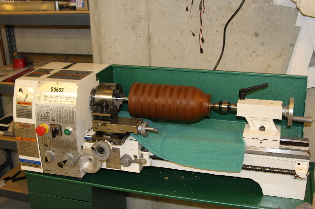
Here's my new lathe. It and the mill both weigh almost 300 lbs, and required quite the operation, just to get them setup in the basement. The look I got from the wife, when I mentioned that I was going to be driving the lawn tractor and it's trailer into and inside the walkout basement was quite entertaining. This, combined with a rented engine lift, got most of the job done of getting them settled into the shop. What you see chucked in the lathe will be part of the next update, and I'm not spilling the beans yet on what this bizarre thing is.
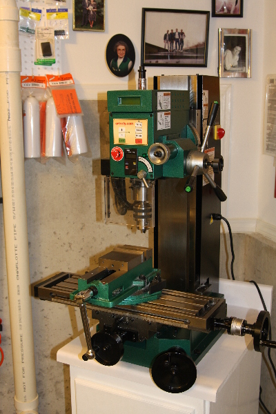
Here's the mill, on a stand that I had to build for it. I had to build a very beefy stand, considering this mill weighs almost 300 lbs. I've very pleased with both the mill and lathe in how rugged they are built and the tolerances I've been able to get with them so far. You also see a vice that I've got bolted to the moving table, that has been trued to it as well.
The lower main gear struts started from a bar of 1 inch by 2 inch by 8 inch aluminum. Part of figuring this out is planning the order that cuts are made. Here is the initial cuts reducing the width where the cylindrical upper part of the strut will be.
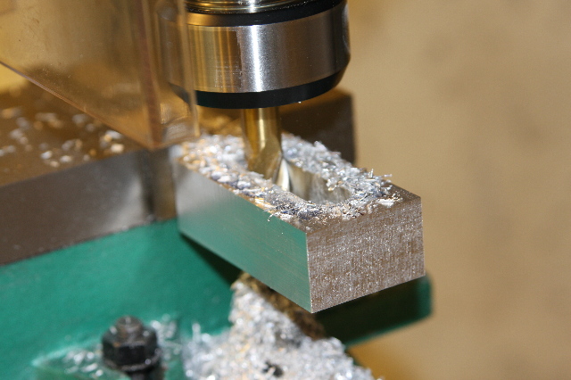
Next up is going to the other end, and while it's still square, removing most of the material from where the middle of 3 tires will go. I've left the bottom closed so that when it's clamped in the lathe, it would not crush the 2 legs together.
Now over to the lathe, and you can see at the top of the photo how I've got it clamped and what I mean about leaving the bottom closed for now. This part was much easier than I thought. I'm making a square thing round, basically. I was expecting it to bang about and make a big noise. Instead it went easy and smooth.
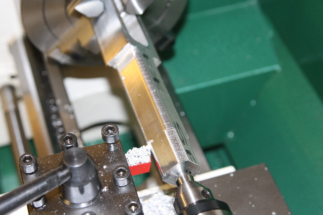
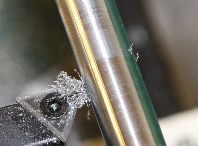
Once I get close to where I'm going, diameter wise, I change the rate that the carriage moves, to a slower speed, and take a shallower cut, to smooth it out. In this very zoomed in shot, you see about 2/1000 of an inch being removed, and the feed rate reduced. You can see how it is getting smoother. You can't even see the individual groves on the top part of this shot with the naked eye, just that it's not as shinny.
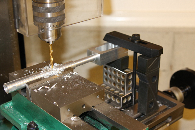
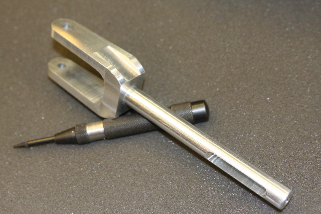
I made the outer (upper) sleeves for the gear very simple to start. When I get it done, I'm going to go back and make a new set that are dead on scale. They were the first things I tried making, and once they turned out good, I decided to make the lower struts dead on scale. They turned out good as well. Anyhow, I needed a cross pin to hold the struts in place, and here you see both being drilled at the same time to ensure a good fit. I'm sure my 3 and 5 year boys would enjoy playing with what looks like building blocks, but are actually a variety of clamping fixtures. This hole would have to be milled out into a slot, in the lower strut, to within 1/1000 of an inch tolerance, for it to slide correctly, but yet not have slop in it.
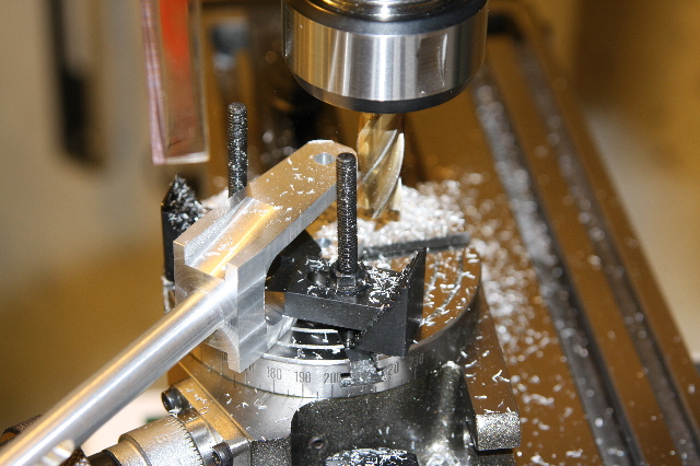
Once the functional parts were done on the struts it was time to make them look more scale like. Here you see a sloped cut on the 'shoulder' of the leg, and me putting to use for the first time my Rotary Table. It's a tool, that you use with a mill, that lets you rotate a part around. Think of it with it's clamps in place, as a vice you can pivot around the cutter. I rounded the bottoms of the of struts, and then put the rounded edges on the top of the shoulders as well.
The finished lower strut. For me not having a clue what I'm doing, on all new gear, I'm very pleased how this is turning out.
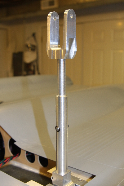
The finished and installed strut. Inside the upper strut, is a compression spring, that is rated to 53 lbs compression over a 1 inch travel. Now a days you can find anything on the Internet. I was perplexed where to find the correct springs, and 10 minutes later I was looking at a chart from a company, that I could pick to within a few pounds of force, the exact springs of my choice. Fun times that we live in....
Head back to the Main Page