3/26/2009
Progress on Many Fronts....
Most of these updates I try to keep to a certain topic or element of the build. However, I'm working on many different elements all at the same time, so this update is a bit of a collection of some odds and ends.
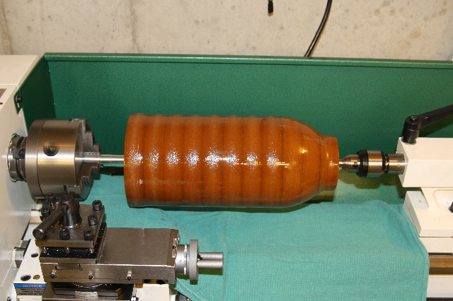
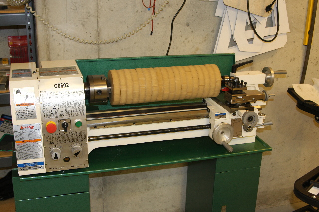
This first photo was revealed a bit in the last update. It is the plug that is being built that will make up the jet engine by-passes. I'm using MDF (medium density fiberboard) on the lathe to shape some of the engine airflow ducting parts. It cuts pretty easy, as it's compressed sawdust glued together, essentially. One interesting thing though, which is because of it's manufacturing process, the outside of the board is denser than the inside. As you see here, I've made a cylinder from many disks of this wood I cut out with a jigsaw. When you cut it with the lathe, the hard parts cut pretty good, but the soft parts fuzz up. So, to make the surface consistent in hardness, I've soaked it with resin after getting it pretty close to the shape. That's why there is a shop towel below the part, so that in case I dripped any resin, while brushing it on, it would not get down in the bed of the lathe.
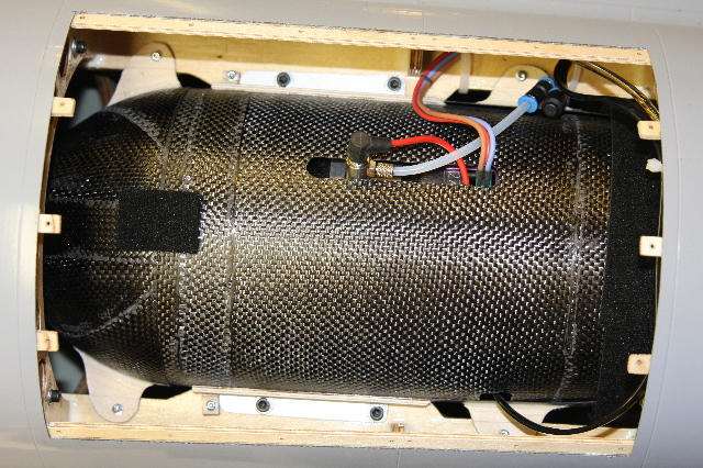
Once the plug is shaped, painted, sanded, and waxed, I was able to lay carbon cloth around it, to make the ductwork that goes around the jet engines, that you see here. Because I want the inside to be smooth, (where the high speed airflow is), I don't make a mold, off of the plug... The plug IS the mold, that you lay your part up around.
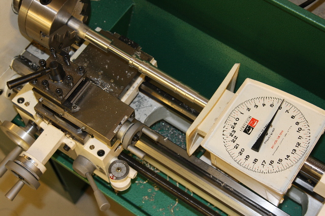
Next up I worked on moving the nose gear strut along. The shot you see here, is confirming the distance of the strut, when under compression, with the expected loads on the nose gear. This way I can confirm that the plane will sit correctly on the ground, when loaded with fuel.
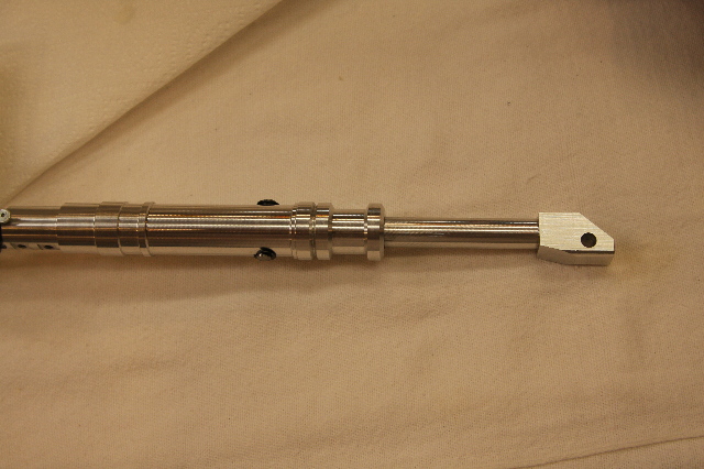
Here is a shot of the completed nose gear strut, including internal spring for shock absorption. You'll note that where the axle goes through on the right side of the photo is offset, in a slightly trailing link manner, as was the full size.
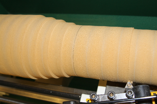
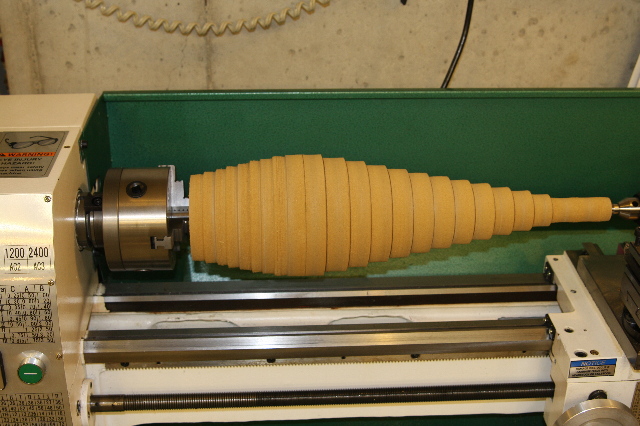
The last part of the update is showing construction of the plug for the inlet spike. Once again, I started with a log, made up of many MDF disks glued together. This thing maxed out the size of my lathe and then some, but I got it to work.
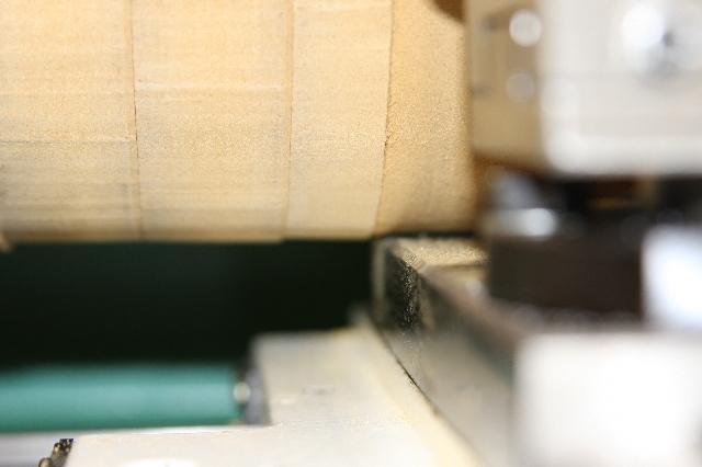
It was so thick in diameter I could not get the bed to initially travel under it. I angled the cutting bit, so that it would be turning down the diameter just enough, just 1/8 of an inch before the bed was coming up behind it.
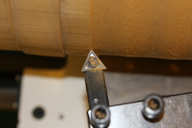
Here is a good shot to see what I mean, about cutting your own clearance as you go.
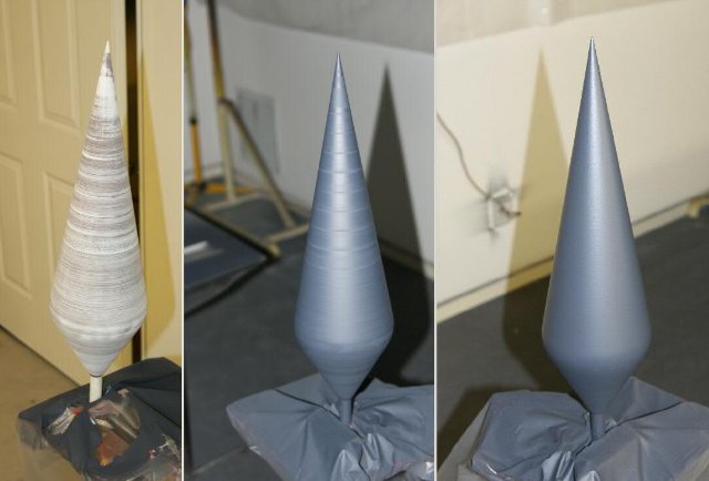
Next up, was a lot of measuring and a lot of math. I needed what would become a cone, that was a specific length and diameter. To get there, I cut it in steps, as shown here.
Getting closer. But I can't take it all the way out to the tip yet, because I need it to hold it steady for now. Getting this tip down good at the end was no easy task.
Here is a collection showing the steps, from soaking with resin....sanding...filler, then painting...more sanding.....more painting...more sanding....
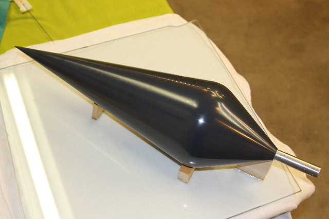
The finished inlet spike, sanded, polished and waxed, now ready for the jigs and fences to be setup to make molds around it. The taper on the backside, will flow down and lead into the starter bullet on the front of the jet engine inside the nacelle.
Head back to the Main Page