9/30/2009
Inlet Spikes and Liners
Flying season has been in full swing around here, but there's still progress on the sled. This update is about the inlet / spike area. This was one of the last big technical challenges to think through. The inlet liner is a shallow funnel but is offset a bit. The spike is a very distinctive feature on the full scale and has to be on the model. However, getting a nearly 2 foot long spike to hover in the center of the nacelle, in a 200 mph airflow, just in front a jet engine was not simple. At this stage, they are done, but not test flown. I sure hope they stay attached, or don't get sucked into the engines......
Here we see what I was starting with.... Mounted engine, sitting in it's custom made bypass. You'll note that I've molded in a small lip on the front of the bypass, ready to receive the inlet liner.
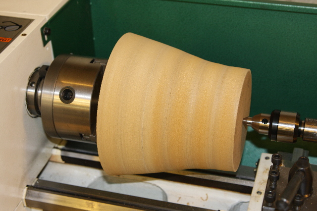
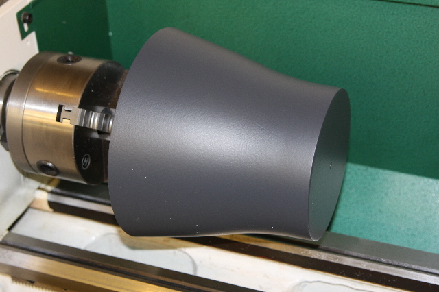
The next 3 photos show prepping the inlet liner plug. I made this a bit long, so that I could make pieces a bit long, and then angle them in the slight offset of the nacelle, and trim off the excess.
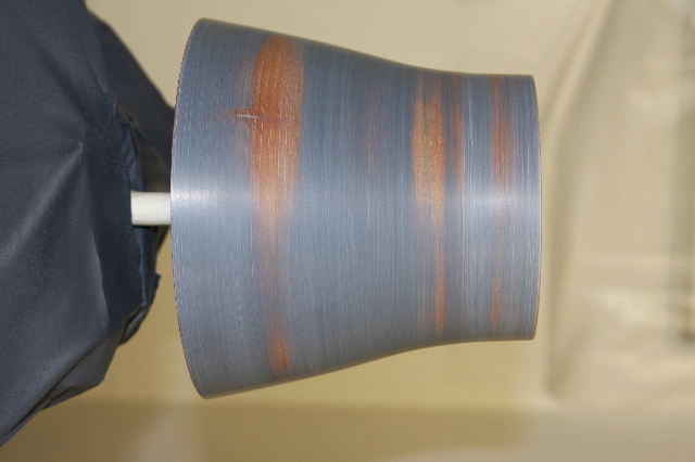
Here's the inlet liner installed. The idea to make them as 2 halves, and then seam them, to a custom fit into the model worked great. It fits on the money in the front and back. The slight mottled look was from how I had to glue them in, which was sitting the plane nose down, and going in through the engine area, and pouring the glue against the outside of the liner, and allowing it to flow forward to the front lip. I used some micro balloons to lighten this a bit, hence the white.
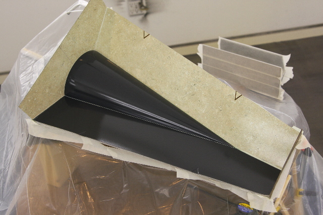
On a previous update you saw the competed spike, both the long pointy part you see outside of the plane, and the taper on the inside that goes in the nacelle. Here you see part way through the mold making process. The bottom mold is done, and the other sides are the now familiar fences in place to make the next mold section.
Completed spike molds. You'll see here the front long molds were made into 3 parts.
The back part had 2 molds cast about it. Based on how I was going to design the spike, I needed to make it as 2 sub assemblies, which would be a front spike and the back part first.
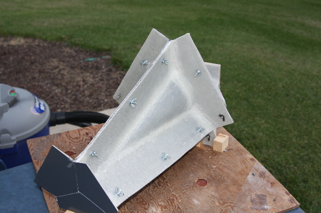
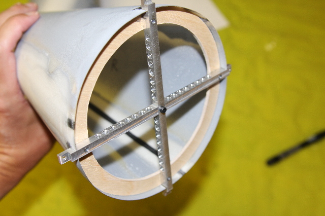
This next shot shows why I needed to make the spike in a front and back part separately. Shown here is the inside of a now finished spike from the molds, with a ½ inch wooden former at the widest part. I then machined an 'X' out aluminum to eventually get 4 mounting lugs that just protrude out the edges of the spikes. It seemed just wrong to bury some great looking metal work with 64 lightening holes in them, but alas, I soon glued on the rear of the spike and hid some great looking metal pieces.
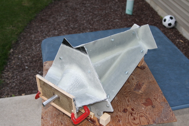
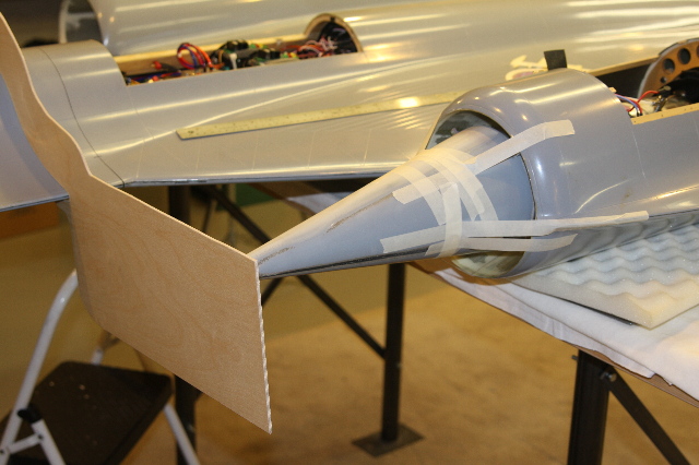
So, now that I've got a spike made and ready to mount, comes the next, really tough question. How do you mount them square? The spikes point slightly down and inward. Obviously both spikes need to be the same amount. I needed a template. Shown here is the spike held temporarily at the precise angle. Then a temple was made that fit the chine like a glove.
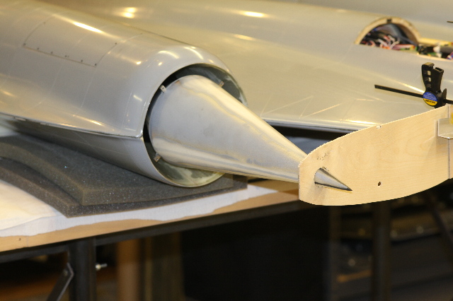
Once the template was made, then a hole was opened up in the proper place, to hold the proper angle on the spike. You can see here, not only the hole, but also, it's holding the spike with no tape, allowing me to now, get in there to make and glue in the attachment lugs into the nacelle.
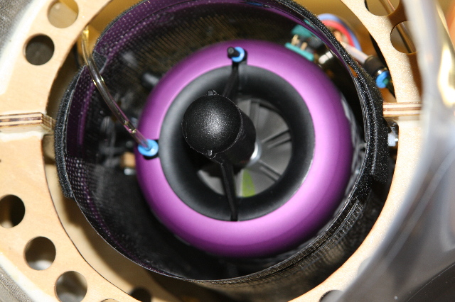
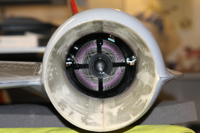
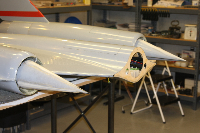
Completed spikes installed. I'm optimistic, that they will hold. If I lift it at the former in the middle of the spike, I can literally lift one side of the plane off the table. Not only are they in there good, the spikes turned out light too. Each one only weighs 5 ounces. Considering the consequences of this part failing, I'm quite anxious to see how it turns out. Currently the plane has had 6 test flights, and so far not a scratch on it, with many things learned. Most have gone well, but a few smaller things have come up that need some redesign work, mostly on the gear doors.
Head back to the Main Page